Les Antennes Souterraines
| |||||||
| Les Travaux de LGV Rota | Les Articles de Layman | Nature et détection des courants universels | Les Antennes Souterraines | Les Courants Universels | Les théories de LGV Rota | ||
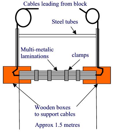
Le bloc est construit avec des sandwiches de triplets de différents métaux. Un certain nombre de ces triplets sont maintenus ensemble pour former le bloc .Voir 1, 2, 3. Les métaux formant le « pain » du sandwich sont maintenus à l'extrémité et ne forment pas un condensateur car ils sont en court-circuit. Le métal central, la « viande » du sandwich est fortement isolé des autres métaux des deux cotés.
Les métaux constitutifs ont chacun leurs courants caractéristiques qui s'unissent pour former un groupe concordant. Cette concordance se produit sans aucune intervention humaine et s'effecture naturellement. Le bloc acquière de ce fait une signature qui correspond à celle du courant universel à étudier. Le bloc est alors accordé, c'est-à-dire « synchronisé », mais cette fois pas uniquement intérieurement mais également avec le groupe du courant universel du lieu. L'effet de résonance entre le bloc et ses courants associés cause l'énergie innée emprisonnée dans le bloc à se libérer sous forme de courants universels, tous les métaux dans le bloc contribuant à amplifier grandement le faible signal d'entrée. Tout ceci se produit naturellement, cependant le processus demande plusieurs années.
Une fois activé, le bloc se trouve dans état qui n'existe que dans les organismes vivants. Il n'est donc pas exagéré de prétendre que le bock est devenu vivant. Les pages dédiées aux applications médicales contiennent de plus amples informations concernant ce sujet (Applications Médicales, Conférence du Dr. Kresser , Essais de diagnostic )
 |
| Fig. 3a. More blocks showing laminated construction and thick cable emerging from one lamination. |
The buried blocks were the energy source. The energy from buried blocks could be used to charge little above-ground blocks, which were in the laboratory, these small blocks were charged by connection to the buried blocks. These small blocks held their energy for some months before requiring recharging.
The small blocks could be used as energy sources for gas discharge lamps of special construction. The electrodes of these lamps consisted of different metals all rendered active which were connected to the small power source blocks. The lamps were filled with low pressure inert gas mixtures and glowed with a cold white light. Although the glow looked similar to common electrical ionisation it was caused by a different mechanism, namely excitation of the intrinsic currents of the metal and inert gases themselves
by the universal currents fed from the power source blocks. Fig.11 shows two different lamp excitation blocks. I will return to the lamps and lamp excitation blocks later.
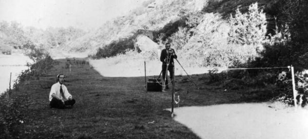
There were other blocks used for medical purposes and also for water location. Detection was done by listening to the currents with a pair of headphones. I must emphasize that none of this involved dowsing methods but was a physical process involving actual listening: Fig 6. As can be seen in Fig. 6 an assistant is listening, while Rota does some other checks.
 |
| Fig. 4 Junction boxes connecting various cables from buried blocks. Note the thickness of some of the cables. |
Typical Probe


